1 Technical Abstract
HP servers provide a management module called iLO (a.k.a. Integrated Lights-Out), which turns on as soon as the power cable is connected, loading a full-blown proprietary operating system. This module has full access to all the firmware, hardware, software, and operating system installed on the server. In addition to managing the server hardware, it allows the admin to remotely turn the server on and off, gain access to the server’s console, and even install an operating system on it.
There are numerous aspects of iLO that make it an ideal utopia for malware and APT groups: Extremely high privileges (above any level of access in the operating system), very low-level access to the hardware, being totally out of the sight of the admins, and security tools, the general lack of knowledge and tools for inspecting iLO and/or protecting it, the persistence it provides for the malware to remain even after changing the operating system, and in particular being always running and never shutting down…
In this report, we analyze a rootkit discovered in-the-wild that hides inside the iLO, cannot be removed by firmware upgrades and can be hidden from the sight for a long time. This malware has been used by hackers for some time and we have been monitoring its performance. As far as we know, this is the first report of the discovery of real-world malware in iLO firmware in the world.
Since analyzing this malware requires some knowledge of the HP iLO firmware architecture, we’ll first give a general overview of the HP iLO architecture. Then, in the next section, we will analyze the discovered malware and its various modules. Finally, in the last section, we will discuss strategies and solutions for protecting iLO.
In addition to this report, we’ve developed some tools to dump iLO firmware and check for infections. We intend to make these available to the general public in the near future. We hope this report will serve as a turning point for attracting more public attention to the security of firmware and creating solutions to protect them.
1.1 Key Points
- The iLO admin panel of HP servers is a safe haven for malware which – after infection – cannot be detected or cleaned up by conventional methods.
- Accessing and infecting iLO is not only possible through the iLO network port, but also through the system administrator or root access to the main operating system. This means that if an intruder has access to a user with administrator/root privileges on the main operating system installed on the server, it can – without needing any further authentication – directly communicate with the iLO, and infect it if it is vulnerable.
- Research over the years has revealed several vulnerabilities in HP iLO that have led to patches and architectural changes by the manufacturer.
- In iLO4 and its earlier versions used on G9 and below servers, there is no Secure-Boot mechanism with an embedded Trusted Root Key in the hardware. So, the firmware of these versions is at more risk of being modified and infected by malware.
- Even if iLO has been updated to the latest version that does not have any known vulnerabilities, it is still possible to downgrade it to a lower version., which makes infecting fully-patched firmware possible. You can only prevent this in the G10 series if a non-default setting is enabled. On earlier servers, it is not possible to prevent the downgrade mechanism.
- Given the above, simple solutions like totally disconnecting the iLO network cable or upgrading firmware to the latest version is NOT enough to prevent malware infection.
- Since 2020, the malware analysis team of Amnpardaz Software Company has discovered a rootkit that adds a malicious module called Implant.ARM.iLOBleed.a to the iLO firmware and modifies a number of original firmware modules. The rootkit silently prevents firmware updates while pretending it to complete. It also provides access to the server hardware; one of the results of which is a complete wipe of the server disks.
- A tool for verifying the integrity of HP iLO firmware will be soon released to the public.
1.2 Indicators Of Compromise (IOC)
While it’s customary to provide hashes as IOCs, we decided that this will not be effective against this malware. Mainly because without having an iLO dump tool at hand, it will be impossible to read the firmware and check its hash. Moreover, the set of real iLO firmware is very small, so taking a whitelist approach is possible and better suited. (i.e. comparing the hash of the firmware to a list of known good hashes).
But if you’re concerned whether your server is infected with this malware or not, you can use a simple method as below:
As noted, the malware – in an attempt to maintain persistence and prevent being cleaned – silently blocks the firmware upgrade process. The malware tries hard at simulating the upgrade process and goes to difficulties of displaying fake “upgraded” versions in the web UI of the iLO and other places, but there is a catch: HP has changed the UI of the iLO considerably. So, you can easily detect the malware presence using “bare eyes”.
Here in Figure 1, you can see two screenshots of iLO-4 firmware, both claiming to be version 2.55. But as you can see, one of them is using the old 2.30 version UI, which used a totally different theme.
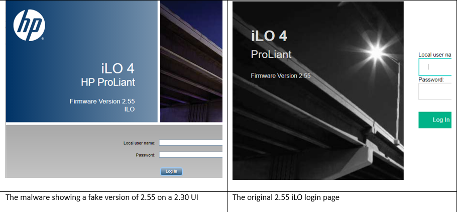
Figure 1 – Comparison of the fake (infected) and the real iLO login page
Of course, like any other IOC, we expect the crooks to find a way around this detection method. But in the meantime, you can use it to easily “spot” the malware. And we hope it to take a – albeit little – work for them to make everything “look” right.
2 HP iLO Technology
HP provides system administrators with iLO technology as means of managing the servers. This technology allows system administrators to remotely access various features of their servers using a special network interface, including:
- Turning the server on and off,
- Configure various hardware and firmware settings,
- Remote access to the system console,
- Install CD / DVD Image remotely,
- Monitor and control many hardware and software indicators of the system remotely
During years, HP has introduced various versions of the iLO firmware for different generations of its servers. Table1 displays these versions.
Table 1 – iLO Firmware versions for different generations of HP servers
| iLO Firmware Series | HP ProLiant Server Generation | The latest version |
| iLO | G2, G3, G4, G6 (under 300 series) | 1.96 – April 2014 |
| iLO 2 | G5 and G6 (above 300 series) | 2.33 – March 2018 |
| iLO 3 | G7 | 1.94 – December 2020 |
| iLO 4 | G8, G9 | 2.79 – November 2021 |
| iLO 5 | G10 | 2.60 – December 2021 |
Due to the critical authority and performance of this firmware interface in all server families, various scenarios for attacking this interface are conceivable. These attacks include obtaining the password of the management interface, exploiting security vulnerabilities, as well as flashing infected firmware instead of the main firmware on the server.
In recent years, a series of studies have been conducted to identify security vulnerabilities in the management interface of HP iLO firmware [1][2][3]. These studies have eventually led to the discovery of a number of vulnerabilities with critical to high and moderate risks. Unfortunately, in recent years, the widespread release of these vulnerabilities and proof-of-concept code snippets has allowed individuals and hacking groups to use these vulnerabilities to attack the network infrastructure of organizations using HP servers in their corporate networks.
2.1 iLO Firmware Architecture
From a hardware point of view, iLO is integrated with the main board of the system and includes the following[2]:
- ARM processor with GLP/Sabine architecture
- Flash memory for firmware storage
- Dedicated RAM
- Dedicated network interface
- A set of hardware ports for communicating with other control units

Figure 2 – iLO firmware scheme
Figure2 displays the schematic of iLO hardware. As can be seen in this figure, the ARM processor connects to the South Bridge via the PCI-Express interface and through it to the server’s main processor. The iLO can also communicate directly with CMOS. This type of connection is for setting variables such as Boot Order, which the iLO management interface will provide to the user.
2.1.1 iLO Processor
The processor used in the iLO hardware is from the 7th and 8th generations of ARM processors. These processors provide good processing power, while considered to be very low consumption. This helps to provide the management interface to the network administrator while the server is in standby (powered-off) mode without consuming too much power and current.
2.1.2 Persistent Storage
The iLO processor can communicate with different memory chips. In particular, two of these chips are discussed in this section. First is the main chip of the system on which the iLO firmware is stored, and is used during the iLO boot sequence to load the firmware.
The second is the chip memory known as the iLO NAND Flash, which is available to the iLO firmware as external system storage. After loading, the iLO firmware uses this storage to save files such as system event logs and history. It’s also the storage space of applications that are running by the iLO operating system.
2.1.3 Connection with the main server
iLO technology as a server management and control unit has direct access to all server hardware components such as memory, processor, input and output ports, and hard disks. Also, the server’s main processor detects the iLO as a PCI module and can communicate with it.
2.2 iLO Firmware Structure
The iLO firmware is stored as a binary file within the SPI flash drive (often 16 MB in size). As can be seen in theFigure3, this firmware consists of 3 main parts including the Boot Loader, operating system kernel, and user-mode modules. Of these 3 sections, only the Boot Loader section is not encrypted, but the other two are compressed (with LZMA algorithm) and include a signature. All iLO firmware executable content is C-code compiled with ARM architecture.

Figure 3 – The internal structure of the iLO firmware
From a software perspective, iLO provides a variety of services such as Web Server and SSH Server for server administrators. In fact, iLO is a complete operating system that boots and makes its services available as soon as the system is plugged into the power grid, even when the hosting server is off.
At the time iLO is booting up, each section will check the next section’s integrity before running any part of it. Thus, the Boot Loader section will be responsible for validating the signature, extracting compression, and loading the Kernel section. The Kernel section will also be responsible for validating the signatures, extracting compression, and loading user-mode modules.
The operating system used in the iLO firmware is a real-time operating system called Integrity developed by Green Hills Software and is responsible for performing tasks in the user area. The user area is actually an ELF binary file with ARM architecture developed and packaged by HP. This file has various modules, each of which has a specific task. Each task is a process with dedicated virtual memory space and a set of threads that runs in the user area. In the following sections of this document, some of the most important iLO modules will be described.
2.3 iLO Modules
Figure4 shows a number of UserLand modules in the iLO 4 firmware. Some of the most important modules will be introduced in the next sections.
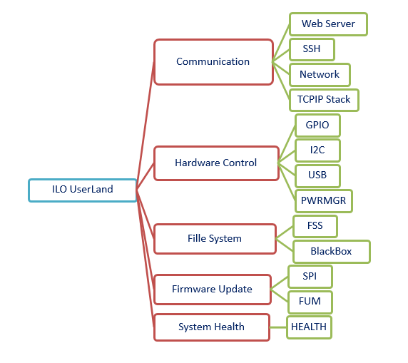
Figure 4 – A number of UserLand modules in the iLO 4 firmware
2.3.1 Web Server Module: iLO Web Management Interface
The Web Server module is responsible for providing the iLO management interface in the form of a web service. This module contains sections such as a web interface, an XML programming interface, a Redfish programming interface, and a remote control console.
The connection to the Web Server module can be HTTP or HTTPS. This module has four processing threads, each of which is responsible for managing and responding to one of the connections made with the module. Each connection request is processed line by line, its content is analyzed, and if the authentication and access level are correct, the appropriate response is provided. Although access to almost all web pages requires user authentication, some data is available in XML format without going through the authentication process.
2.3.2 CHIF Module: Connection with the Host OS
CHIF module is one of the modules in iLO that communicates with the CPU and server memory components and transmits messages between the iLO and the host operating system. Briefly, the tasks of this module can be listed as follows[3]:
- Waiting to receive a message from the server’s main operating system
- Send the received message to the message processing unit (Command Handler) according to the message type
- Redirect specific messages to the related modules for processing
The messages and commands sent to this module do not go through any authentication process by default.
2.3.3 FUM Module: Firmware Update
The main task of the FUM module is to update iLO firmware. This task is possible in three ways:
- Through the HP Intelligent Provisioning management interface
- Using the host operating system installed on the server and accessing the PCI-E interface
- Remotely via the iLO web interface management interface
The FUM module performs the firmware update operation in 5 steps[3]:
- The new firmware file is received through the host server or Web Server module.
- The new firmware file is sent to the FUM module.
- The FUM module examines and validates the new firmware file’s digital signature.
- The FUM module asks the kernel to also validate the new firmware file’s integrity.
- Finally, the FUM module sends the new firmware to the SPI module to program it on the SPI flash memory.

Figure 5 – iLO firmware update process by FUM module
In this process, firmware’s integrity is verified by checking its digital signature, so that no module is added or changed from the original firmware provided by HP. An important point is that generally, it is possible to downgrade to a lower version of the firmware.
2.3.4 SPI Module: Access to Flash Memory
The main function of this module is to communicate with the SPI flash memory containing the iLO firmware and the server’s BIOS firmware. This module provides the low-level interface for reading, erasing, and writing firmware on the related flash memory chip. As mentioned earlier, parts of the iLO firmware update operation are performed through this module.
2.3.5 ConAppCli Module: Console (Command Line) Service
This module is responsible for providing the command line user interface service for receiving the server administrator’s commands. These commands can be such as user management, power management, viewing system events, etc.
2.3.6 SSH module: Remote Command Line
In addition to the web interface, the iLO firmware provides the user with an encrypted shell service using the SSH protocol. Through this module, the user can communicate with the firmware via port 22 and execute a set of commands.
2.3.7 Health Module: Monitor System Components
The task of this module is to periodically check the system status, and record server events. The system status includes operating temperature, fan speed, power supply status, the status of system memory, network, processors, etc.
2.3.8 BlackBox Module: Black Box System
This module acts as a server “black box”. Many sensitive and vital system information and events that are recorded by the Health module, are then compressed and stored by this module on a daily basis.
2.3.9 Other Modules
In addition to the modules mentioned in the previous sections, the iLO firmware has a variety of other modules, each of which has a specific task in the UserLand section. Modules such as SNMP, SNTP, and SVCSiLO are responsible for system and network management tasks, and modules such as USB, GPIO, and I2C provide iLO control access to server hardware components.
3 Malware Analysis of Implant.ARM.iLOBleed.a
In this section, we provide a technical analysis of the implant discovered in the HP iLO firmware.
When our security analysis team discovered the malware, the attackers had decided to wipe the server’s disks and completely hide their tracks. Interestingly, the attackers were not satisfied with one-time destruction and set the malware to repeatedly perform the data destruction at intervals. Maybe they thought that this way if the system administrator reinstalls the operating system, the entire hard drive will be destroyed again after a while. Clearly, they didn’t think their malware will be found.
But unlike other “wiper” malware, this is not a one-time hit-and-run disposable malware. It is designed to stay under the radar for extended periods. One of the important features of this malware is the manipulation of the iLO firmware upgrade routine so that if the system administrator tries to upgrade the iLO firmware to a new version, the malware simulates the version change while preventing the upgrade routine. To this end, the malware pretends the upgrade to be successful, with all the right messages and logs. Even the exact number of firmware versions is extracted and displayed in appropriate places in the web console and other locations, although in fact no upgrade has been performed.
This alone shows that the purpose of this malware is to be a rootkit with maximum stealth and to hide from all security inspections. A malware that, by hiding in one of the most powerful processing resources (which is always on), is able to execute any commands received from an attacker, without ever being detected.
Naturally, the cost of performing such an attack puts it in the category of APTs. But using such powerful and costly malware for something like data destruction, a task that increases the likelihood of malware being detected seems to be a blatant mistake on the part of these crooks.
You can read more technical tips about this malware in the next sections.
3.1 iLO Dump Utility
The first step in checking for firmware infection is to prepare a copy or to check the so-called dump of the firmware.
Unfortunately, HP has not provided a tool or method to test and read the iLO firmware. For this purpose, the preparation of a tool for firmware dumping was put on the agenda, which eventually became a Padvish iLO Scanner tool that evolved into two versions:
- Scanning from within the host operating system: As mentioned, iLO firmware is available as a PCI-Express card through the main processor and operating system installed on the system. HP has introduced a tool called flash_ilo for various operating systems, in order to allow updating the firmware to newer versions. However, this tool only allows you to write the firmware and does not allow you to read the existing firmware. To this end, based on the knowledge obtained on the iLO, we were able to develop a tool to read the firmware and create a dump from it.
- Scanning through the iLO network port: Because scanning through the host operating system may not always be possible, and it may be difficult for the network administrators to perform on production servers, or in large quantities, another method for scanning the firmware was considered. This version of the scanner allows dumping the firmware, by using some of the known vulnerabilities on the previous iLO version, allowing it to execute code remotely on the vulnerable firmware. Due to the use of vulnerabilities, this version is only able to dump the HP iLO4 firmware which has a version in the range of 2.30 to 2.50.
3.2 Infected firmware analysis
After making a copy of server firmware, it should be compared to the original firmware versions. Implant.ARM.iLOBleed.a malware is based on version 2.30 of the iLO firmware. Accordingly, the difference between this infected version and the original version is depicted in the following figure (Figure 6).


Figure 6 – Firmware Signature Difference: (Top) Infected dump obtained; (Bottom) Original version provided by the HP Company
In a closer look, the components of both firmware at the file system level and the modules were also compared and are shown in Table 2.
Table 2 – Compare the signatures of the firmware modules of the infected system with the original version
| Difference (Bytes) | MD5 (Infected) | MD5 (Original) | Module Name |
| 15.625MB | 4f8417af3a6f75780e09c5792397a05f | 98af47cb8cacb25abd333d8a1a752c6b | hpimage.bin |
| 0 | 8433650ef98fd8790877e6616c02b66c | 8433650ef98fd8790877e6616c02b66c | hpimage.hdr |
| 0 | ae22d82a3e954ecf911b834463dbfbbe | ae22d82a3e954ecf911b834463dbfbbe | bootloader.hdr |
| 5 B | 1fdb4270665177ecb1c9708039bab934 | 20ff78c6604563c27b6f9c75775c9306 | bootloader.bin |
| 2 B | 7df3b258ca3c12f0f8de77469456e25d | e1b1244fead44f73efb7b559e9d719c9 | kernel_main.hdr |
| 12 B | 9ab97c5b03664da18ab1f775dc11c200 | bacc259ea63785607faf2dab6939a2db | kernel_main.bin |
| 2 B | 7df3b258ca3c12f0f8de77469456e25d | e1b1244fead44f73efb7b559e9d719c9 | kernel_recovery.hdr |
| 12 B | 9ab97c5b03664da18ab1f775dc11c200 | bacc259ea63785607faf2dab6939a2db | kernel_recovery.bin |
| 2 B | 64d0143d638885745b241796268eb0b2 | 7db6ebd698fa4862cfde68a546e9a75b | ELF.hdr |
| 15.625MB | bdeeab3994ec5d0b93d961148a6b712d | d16fee481f78ad0275dd29ed271582aa | ELF.bin |
As presented in this table, out of all the modules that make up hpimage.bin, only the two parts of the hpimage header and the bootloader header are the same. In other sections, the difference in the signature indicates a difference between the two files these sections. It can also be seen that most of the changes are related to the ELF.bin module, while other modules have only 2 to 12 changed bytes.
3.2.1 Persistence after reboots
One of the concerns of developers of any type of malware is that the system must “remain” infected after the malware initially enters the system.
As we previously detailed in the “iLO Firmware Structure” section, in the iLO startup process, the bootloader module is responsible for validating the signature of the operating system kernel, and the kernel of the system is responsible for validating the signature of the user-mode modules. Therefore, if the attacker wants to create a backdoor on the iLO firmware, in addition to inserting the backdoor, which is basically done in the ELF.bin file, it is necessary to disable the validation mechanism in both the operating system kernel and consequently in the bootloader.

Figure 7 – Disabling the validation process of the operating system kernel and user-mode modules
Figure 7 briefly depicts the process of bypassing the validation process of the operating system kernel and the user-mode modules[2]: After extracting the three main parts bootloader.bin, kernel.bin, and ELF.bin through reverse engineering, the attacker finds the addresses of the functions that perform signature verification and validation operations in both bootloader and kernel and replaces them with the NOP command. Finally, the modified files are grouped together to form a complete HP Image file and are written to the SPI flash memory as the new firmware. After a reboot, it can be seen that the infected firmware loads the back door without any problems.
3.2.2 Malware Modules Analysis
3.2.2.1 Boot Loader section
As shown in Table 2, the Boot Loader has 5 bytes changed from the original firmware. Detailed analysis of these bytes shows that this difference is due to a change in the function responsible for validating the operating system kernel, and is disabling this process by replacing NOP commands. (Figure 8)

Figure 8 – Disabling the signature validation function in the Bootloader
3.2.2.2 Kernel section
As shown in Table 2, the kernel has 12 bytes changed from the original firmware. The more detailed analysis of this change shows that this difference is due to a change in the function responsible for validating the UserLand signature and disabling this process by replacing 3 NOP commands (Figure 9)

Figure 9 – Disabling the signature validation function in the Kernel
3.2.2.3 UserLand section
Extracting the UserLand section of the infected firmware and comparing its content with the original version, indicates that a file is deleted (sectionInfo) and a new module is added (called newELF containing 17 separate sections). See Figure 10. Also, in addition to adding the new malware module, a number of modules in the original version have also changed.

Figure 10 – Modified files in the infected system hardware
In this section, a comparison is made between the modules of the original version and the modified modules in this malware, the results of which are shown in Table 3.
Table 3 – iLO Version with NewELF comparison with the original version
| New Op | Old Op | Function | Offset | File Name |
| BL | MOV | sub_10070 | 0x280 | Chif.ELF.text |
| BL | ADD | sub_19BD0 | 0x9c28 | Chif.ELF.text |
| BL | SUB | sub_10210 | 0x218 | Webserver.ELF.text |
| BL | BL | sub_3AEC4 | 0x2af80 | Webserver.ELF.text |
| BL | BL | sub_3AEC4 | 0x2b024 | Webserver.ELF.text |
| BL | MOV | sub_152AC | 0x5840 | Health.ELF.text |
| BL | MOV | sub_47B1C | 0x37b30 | Health.ELF.text |
| BL | BLNE | sub_13B68 | 0x4324 | Fum.ELF.text |
| BL | MOV | sub_13B68 | 0x43b8 | Fum.ELF.text |
| BL | BL | sub_13B68 | 0x4400 | Fum.ELF.text |
| BL | MOV | sub_14720 | 0x4738 | Fum.ELF.text |
| BL | SUB | sub_109A4 | 0x9ac | Json_dsp.ELF.text |
| BL | BL | sub_19F48 | 0xa564 | Json_dsp.ELF.text |
| BL | BL | sub_73190 | 0x6324c | Json_dsp.ELF.text |
| BL | BL | sub_73190 | 0x632f0 | Json_dsp.ELF.text |
| BL | MOV | sub_114EC | 0x1578 | SvcsiLO.ELF.text |
| BL | BL | sub_14300 | 0x4310 | SvcsiLO.ELF.text |
| BL | MOV | sub_1F378 | 0xf388 | SvcsiLO.ELF.text |
3.2.3 Malware Artifacts
The Implant.ARM.iLOBleed.a malware creates 3 files inside the workspace storage of the iLO (a.k.a NAND Flash). The path and even the name of these files seem to have been configurable via a configurator module. In the malware sample, we obtained, these three files are named lifesignal.bin, schedule.bin, and fakefwdata.bin (Table4 ).
Table4 – The three files used by the malware
| File name | Storage Path | Related modules |
| lifesignal.bin | i:\vol0\logs\lifesignal.bin | Chif.tool – NewELF.ELF |
| schedule.bin | i:\vol0\logs\schedule.bin | NewELF |
| fakefwdata.bin | i:\vol0\logs\fakefwdata.bin | Fum.tool – NewELF.ELF |
If the system administrator tries to upgrade the firmware version of their server, the malware – while preventing and simulating the firmware upgrade operation to deceive the system administrator – enters the information of this operation in the fakefwdata.bin file.
The schedule.bin file, as its name indicates, is used to schedule the disk-wipe operation. Inside this file, there are two 4-byte integers stored: A counter, and a date epoch. The first 4-byte number (counter) is set to an initial value and is decreased by one each time the disk-wipe process is performed. This operation is repeated in periods until the counter reaches zero. The second number (date) indicates the starting date of the disk-wipe process (Figure 11).

Figure 11 –File schedule.bin’s content
3.2.4 Inside “newELF” Module
This module is a complete ELF that is added to the end of the Boottable and increases the number of processes by one unit. This ELF, like other ELFs in this firmware, consists of several basic components. The first part is NewELF.ELF.Initial.text, which, unlike other ELFs, is not empty and contains code. A closer look reveals that this section is very similar to ConAppCLI.ELF.text, which is one of the main modules of the iLO hardware. Table 5 shows a general comparison made between these two modules that show their differences. These similarities indicate that the basic structure of Implant.ARM.iLOBleed.a malware is based on the functions of the ConAppCLi module.
Table 5 – Comparison between ConAppCLI.ELF.text and NewELF.ELF.Initial.text
| NewELF.ELF.Initial.text Opcode | ConAppCli.ELF.text Opode | Function | Offset |
| STMFD | STMFD | sub_10070 | 0x74 |
| SUB | SUB | sub_10070 | 0x7c |
| LDMDB | LDR | sub_10070 | 0x80 |
| Add Zero Buffer | – | End of Old File | 0x91c78 |
The other basic part of malware is NewELF.ELF.text. Figure 12 shows the main function of the malware. One of the main tasks of this function is to set a data structure that determines the main parameters of the malware operation and part of it has been shown in Figure 13. At the beginning of this function, the address of the schedule.bin file is copied to a variable, and the pointer to this address is copied to the 0x0c address of the data structure.

Figure 12 – The main function of the malware
Next, in another function called initOperationConfigFiles, the status of the files required by the malware is checked. In this function, the lifesignal.bin file is created first, and then some conditions are considered:
- If the schedule.bin file exists and has a valid structure, its contents will be copied to addresses 0 to 0x07 of the data structure and the value 0x3 will be written in the lifesignal.bin file.
- If schedule.bin file does not exist in the relevant address, it will be created and filled with initial values. After that, the data structure is completely filled.
- In case the schedule.bin file has an invalid structure, 0x9 is written in the lifesignal.bin file.

Figure 13 – Data structure of malware operational parameters
As previously described, the schedule.bin file consists of two 4-byte numbers. At the beginning of the operation, in the initOperationConfigFiles function, the counter number is set to the maxOperationCount (address 0x24 data structure) and the date number is set to the desired time and the day of the command execution. In one sample of the malware, the maximum value of repeated operations is set to 0x2 and in another sample to 0x3e8 (equivalent to 1000 times).
After checking the suitable conditions for performing the destruction operation, the operation starts in the startPeriodicOperation function (Figure 14). This function in the first step creates and fills an array of data structures with the maximum length of the operation. Each of these data structures is evaluated with different values of execution time. This setting is such that the malware adds various multiples of the operation period (for example, 12 hours) to an initial waiting time (for example, 36 hours) and records this value at the 0x1C address of each data structure. In this case, the operation starts after the waiting time (36 hours) from the time recorded in the schedule.bin file and is repeated in each period. Finally, the startWipeOperation function is called, which performs the disk destruction operation.

Figure 14 – Function body of startPeriodicOperation
The startWipeOperation function performs a destruction operation in a loop which has been shown in Figure 15. At the beginning of this loop, a function called GetAndValidateOperationParameters checks the accuracy of the operation parameters and calculates the number of operations remaining. In fact, the number of operations performed in a variable called SuccessfulOperationCount is extracted and is checked so that the obtained number does not exceed the maximum value of the counter.

Figure 15 – Function body of startWipeOperation
The next function is the WaitForNextOperationTarget function whose content is displayed in Figure 16. The duty of this function is to create an interruption in the main loop until the next operation time is reached. At the specified time, this function exits its loop and the main loop of operation continues to operate.

Figure 16 – Function body of WaitForNextOperationTarget
In the next part of the main loop, the wipe disk operation is performed and the server’s hard disks are completely wiped. After the destruction operation is completed, the schedule.bin file is updated by the DecrementOperationCount function and a counter is reduced. The body of the DecrementOperationCount function has been shown in Figure 17.

Figure 17 – Function body of DecrementOperationCount
3.2.5 Analysis of Modified Modules
This malware contains modified versions of some of the iLO modules. Some of these modules are modified to prevent the original functionality or otherwise change it. There are 6 modified modules in the malware as listed below:
Table 6 – Malware modified modules
| Module Name | Description |
| .chif.tools | Change the message exchange channel between the iLO and the server |
| .fum.tools | Bypass the firmware update process to maintain infected firmware |
| .webserver.tools | Change admin web interface to display invalid iLO software version information |
| .health.tools | Modify server event logging module to prevent logging malware’s operations |
| .svcsiLO.tools | Modify the multi-threaded core of the iLO operating system |
| .json_dsp.tools | Unspecified |
4 Conclusion
Firmware security has emerged in recent years as an important issue in IT security, while in practice it is not given enough attention yet. Due to the features and high level of access that the HP iLO management tool has, it requires special protection methods. Unfortunately, the lack of tools and information and the proprietary nature of the iLO technology prohibits many security researchers to study these systems. Much worse, although research published by security researchers in the past has examined the possibility of hypothetical malware being embedded in the software, there is still no publicly available solution to “detect” the infection and eliminate it if it occurs[2].
Another important point is that there are methods to access and infect iLO both through the network and through the host operating system. This means that even if the iLO network cable is completely disconnected, there is still the possibility of infection with the malware. Interestingly, there is no way to turn off or disable iLO completely in case it is not needed.
These issues indicate the need for preventive security measures to improve the security of the firmware, such as updating to the latest version provided by the manufacturer, changing admin passwords and isolating the iLO network from the operating network, and finally periodically monitoring the firmware’s status in terms of security parameters and potential infection.
4.1 Suggestions for Protecting iLO Firmware
- Do not connect the iLO network interface to the operating network and improvise a completely separate network
- Periodically update the iLO firmware version to the latest official release from HP
- Perform iLO security settings on HP servers, and disable downgrade for G10 servers
- Use defense-in-depth strategies to reduce risk and detect intrusions before reaching the iLO
- Periodically use the iLO Scanner tool to detect potential vulnerabilities, malware, and backdoors in the current version of the iLO Server firmware
5References
[1] F. Périgaud, A. Gazet, and J. Czarny, “Subverting your server through its BMC: the HPE iLO4 case,” Recon, 2018.[2] F. Périgaud, A. Gazet, and J. Czarny, “Backdooring your server through its BMC: the HPE iLO4 case,” SSTIC, 2018.
[3] F. Périgaud, A. Gazet, and J. Czarny, “Turning your BMC into a revolving door,” ZeroNights, 2018.